conf t
!
hostname RT1
!
interface ethernet0/0
ip address 10.1.1.1 255.255.255.0
no shutdown
!
logging console
!
end
conf t
!
hostname RT2
!
interface ethernet0/0
ip address 10.1.1.2 255.255.255.0
no shutdown
!
logging console
!
end
conf t
!
hostname SW1
!
logging console
!
end
VLAN (Virtual LAN) は1つのネットワークを論理的に分割するための技術です。
物理的に同じスイッチに接続されていても、VLAN により別々のネットワークとして扱うことができます。
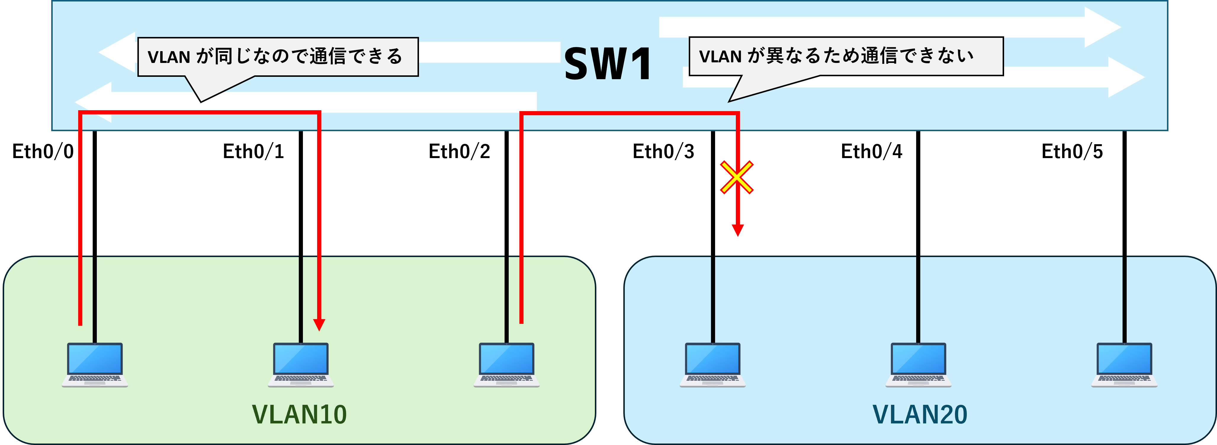
VLAN を使用することで、同一のスイッチ内でも異なる VLAN 間は仮想的に分割されているため通信できません。

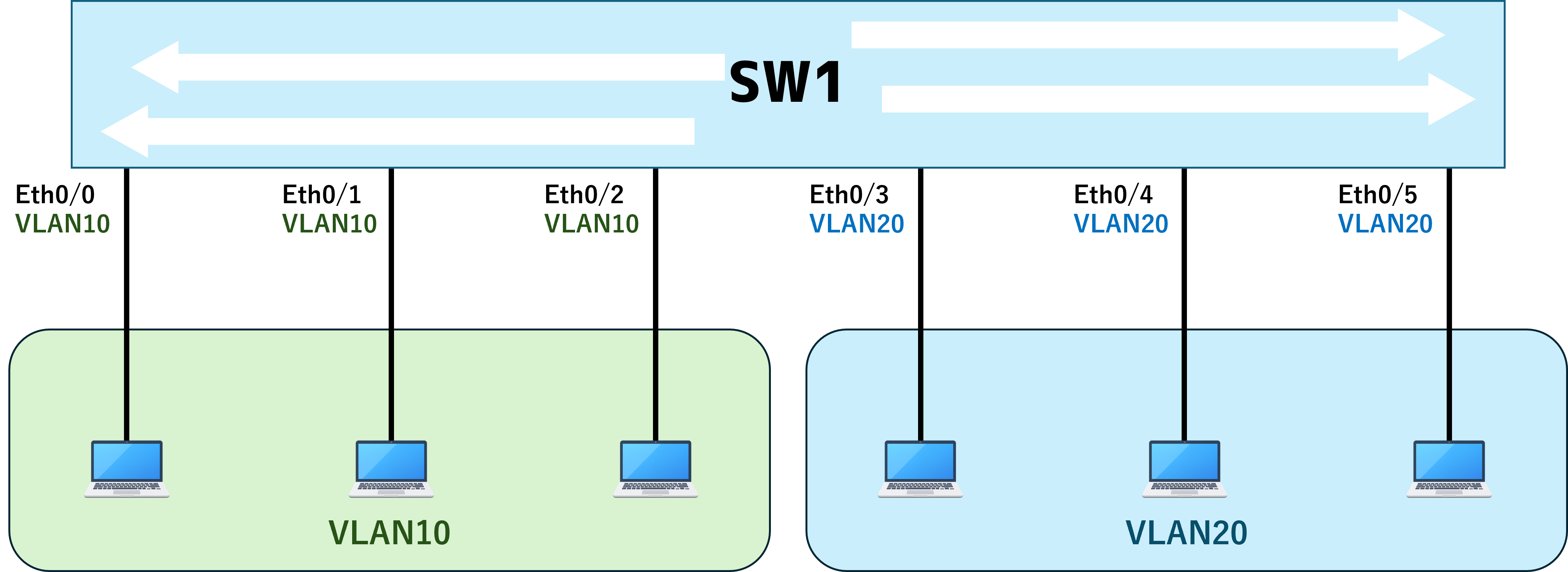
スイッチはインタフェースに VLAN を割り当てることができ、そのインタフェースから受信した通信を設定されている VLAN として内部処理します。

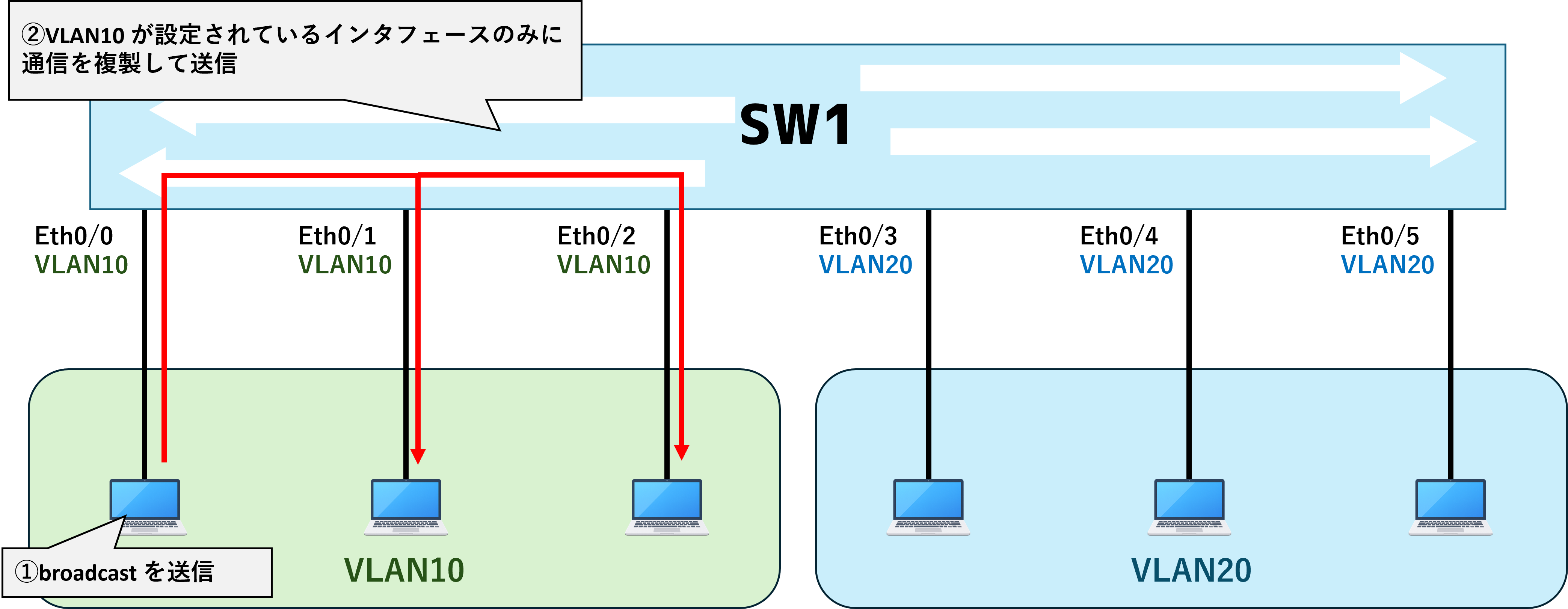
VLAN を分けることでどのような変化が生じるかというと、broadcast 通信の範囲を限定することができます。この broadcast 通信の届く範囲をブロードキャストドメインと呼びます。
例えば、VLAN10 が設定されたインタフェースに接続された PC からの broadcast は同じ VLAN10 のインタフェースに接続された機器に送信されますが、VLAN20 のインタフェースからは送信されません。

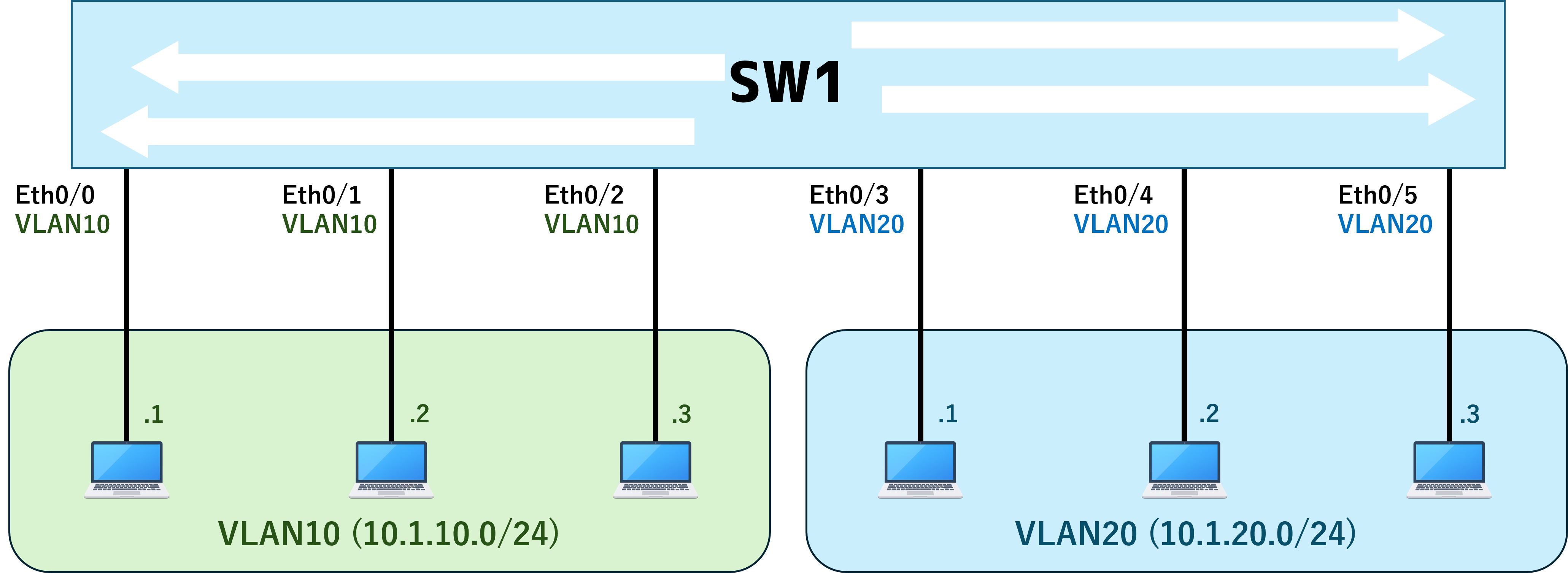
そして、一般的には VLAN に対してネットワークアドレスを紐づけます。
例えば
VLAN 10 = 10.1.10.0/24
VLAN 20 = 10.1.20.0/24
といった形です。

VLAN (ネットワーク)間を通信させる場合は Router や L3SW を用いて VLAN 同士の接点を設けます。
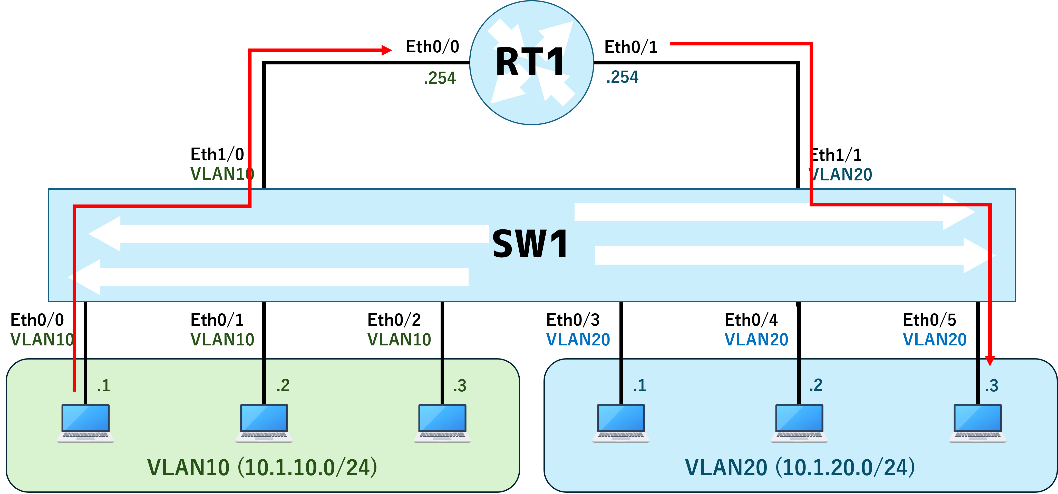
例えばこのような構成にすると、VLAN10 (10.1.10.0/24) に属する PC(10.1.10.1) は RT1 (10.1.10.254) をゲートウェイとして通信します。
そして、 RT1 は VLAN10 (10.1.10.0/24) と VLAN20 (10.1.20.0/24) の両方を持っているので、ここでルーティングし VLAN20 に属する PC (10.1.20.3) に通信を転送できます。

このように VLAN を用いてネットワークを仮想的に分割することで
・broadcast の範囲を限定的にすることで通信量を抑える
・ネットワークの用途ごとに VLAN を分けることで管理性が高まる
といったメリットがあります。
VLAN の大まかな処理と用途は上記の通りになるので、次は実際に検証環境を用いて VLAN の設定や動作を確認していきます。
検証環境で SW1 の現在の設定状況を確認していきます。
まず、Switch が持つ VLAN は以下コマンドで確認できます。
IOS/IOS-XE では default で VLAN1, VLAN1002 ~ 1005 が作成されており、すべての switchport は VLAN1 が割り当てられています。
SW1#show vlan
VLAN Name Status Ports
---- -------------------------------- --------- -------------------------------
1 default active Et0/0, Et0/1, Et0/2, Et0/3
1002 fddi-default act/unsup
1003 token-ring-default act/unsup
1004 fddinet-default act/unsup
1005 trnet-default act/unsup
VLAN Type SAID MTU Parent RingNo BridgeNo Stp BrdgMode Trans1 Trans2
---- ----- ---------- ----- ------ ------ -------- ---- -------- ------ ------
1 enet 100001 1500 - - - - - 0 0
1002 fddi 101002 1500 - - - - - 0 0
1003 tr 101003 1500 - - - - - 0 0
1004 fdnet 101004 1500 - - - ieee - 0 0
1005 trnet 101005 1500 - - - ibm - 0 0
Remote SPAN VLANs
------------------------------------------------------------------------------
Primary Secondary Type Ports
------- --------- ----------------- ------------------------------------------
VLAN Name Status Ports
---- -------------------------------- --------- -------------------------------
そのため、今回は SW1 に対して構成図と同じ構成になるよう以下の設定を追加していきます。
まず VLAN 10 を作成します。
VLAN 作成は以下のコマンドを使用します。
(config)#vlan [1-4094]
今回は VLAN 10 を作成するため以下のように設定します。
SW1(config)#vlan 10
すると VLAN 10 が新規に作成されたことが show command で確認できます。しかし、まだどのインタフェースにも VLAN 10 は割り当てられていません。
※brief option を使用すると簡易表示が出来ます。
SW1#show vlan brief
VLAN Name Status Ports
---- -------------------------------- --------- -------------------------------
1 default active Et0/0, Et0/1, Et0/2, Et0/3
10 VLAN0010 active
1002 fddi-default act/unsup
1003 token-ring-default act/unsup
1004 fddinet-default act/unsup
1005 trnet-default act/unsup
続いて VLAN 10 を Eth0/0 に割り当ててみます。
switch には access port と trunk port という概念が存在し、access port は VLAN を1つ、trunk port は VLAN を複数割り当てることができます。
※trunk port の詳細は次回以降に解説。
PC といった端末を接続する場合は VLAN が1つでよいので、一般的に access port を設定します。
設定方法は以下の通りです。
(config)#interface [interface name]
(config-if)#switchport mode access
(config-if)#switchport access vlan [1-4094]
Eth0/0 に VLAN 10 を割り当てる際の設定は以下の通りです。
SW1(config)#interface ethernet0/0
SW1(config-if)#switchport mode access
SW1(config-if)#switchport access vlan 10
設定すると、Eth0/0 に VLAN 10 が割り当てられたことがわかります。
SW1#show vlan brief
VLAN Name Status Ports
---- -------------------------------- --------- -------------------------------
1 default active Et0/1, Et0/2, Et0/3
10 VLAN0010 active Et0/0
1002 fddi-default act/unsup
1003 token-ring-default act/unsup
1004 fddinet-default act/unsup
1005 trnet-default act/unsup
そして、この状態で RT1 (10.1.1.1) から RT2 (10.1.1.2) に疎通確認をしてみます。すると、結果は疎通不可です。
RT1#ping 10.1.1.2
Type escape sequence to abort.
Sending 5, 100-byte ICMP Echos to 10.1.1.2, timeout is 2 seconds:
.....
Success rate is 0 percent (0/5)
これは RT1 と RT2 は同じネットワークセグメントに属しているものの、VLAN が異なることが原因です。
Switch は通信を受信したインタフェースに設定されている VLAN として内部処理するため、RT1 からの通信は VLAN 10 として処理されます。
そして、Switch は MAC address table を参照し、VLAN 10 が設定されているインターフェースから送信します。
現状は Eth0/1 が VLAN 1 となっているため、Switch 送信できず通信不可となっています。
※MAC address table には
・どの VLAN で
・どの MAC address を
・どの Type (STATIC or DYNAMIC) で
・どの Port から学習したかが1行ずつ登録されています。
SW1#show mac address-table
Mac Address Table
-------------------------------------------
Vlan Mac Address Type Ports
---- ----------- -------- -----
1 aabb.cc00.1f00 DYNAMIC Et0/1 <<<RT2 の MAC address
10 aabb.cc00.1e00 DYNAMIC Et0/0 <<<RT1 の MAC address
Total Mac Addresses for this criterion: 2
そのため、構成図通りに SW1 の Eth0/1 も VLAN10 を割り当てます。
SW1(config)#interface ethernet0/1
SW1(config-if)#switchport mode access
SW1(config-if)#switchport access vlan 10
設定すると、Eth0/1 に VLAN 10 が割り当てられたことがわかります。
SW1#show vlan brief
VLAN Name Status Ports
---- -------------------------------- --------- -------------------------------
1 default active Et0/2, Et0/3
10 VLAN0010 active Et0/0, Et0/1
1002 fddi-default act/unsup
1003 token-ring-default act/unsup
1004 fddinet-default act/unsup
1005 trnet-default act/unsup
この状態で再び RT1 (10.1.1.1) から RT2 (10.1.1.2) に ping を実行してみます。すると、今回は通信が成功しました。
RT1#ping 10.1.1.2
Type escape sequence to abort.
Sending 5, 100-byte ICMP Echos to 10.1.1.2, timeout is 2 seconds:
!!!!!
Success rate is 100 percent (5/5), round-trip min/avg/max = 1/1/1 ms
SW1 の MAC address table を確認すると、どちらの Entry も VLAN10 となっており、これにより通信できていることがわかります。
SW1#show mac address-table
Mac Address Table
-------------------------------------------
Vlan Mac Address Type Ports
---- ----------- -------- -----
10 aabb.cc00.1e00 DYNAMIC Et0/0
10 aabb.cc00.1f00 DYNAMIC Et0/1
Total Mac Addresses for this criterion: 2
インタフェースごとの MAC address は以下のコマンドで確認できます。
RT1#show interfaces ethernet0/0
Ethernet0/0 is up, line protocol is up
Hardware is AmdP2, address is aabb.cc00.1e00 (bia aabb.cc00.1e00)
Internet address is 10.1.1.1/24
MTU 1500 bytes, BW 10000 Kbit/sec, DLY 1000 usec,
reliability 255/255, txload 1/255, rxload 1/255
Encapsulation ARPA, loopback not set
Keepalive set (10 sec)
ARP type: ARPA, ARP Timeout 04:00:00
Last input 00:00:00, output 00:00:06, output hang never
Last clearing of "show interface" counters never
Input queue: 0/75/0/0 (size/max/drops/flushes); Total output drops: 0
Queueing strategy: fifo
Output queue: 0/40 (size/max)
5 minute input rate 0 bits/sec, 0 packets/sec
5 minute output rate 0 bits/sec, 0 packets/sec
37231 packets input, 2401854 bytes, 0 no buffer
Received 37217 broadcasts (0 IP multicasts)
0 runts, 0 giants, 0 throttles
0 input errors, 0 CRC, 0 frame, 0 overrun, 0 ignored
0 input packets with dribble condition detected
8025 packets output, 907362 bytes, 0 underruns
Output 1258 broadcasts (0 IP multicasts)
0 output errors, 0 collisions, 2 interface resets
2219 unknown protocol drops
0 babbles, 0 late collision, 0 deferred
0 lost carrier, 0 no carrier
0 output buffer failures, 0 output buffers swapped out

VLAN の動作と用途、Switch の処理動作を理解することは非常に重要です。
ログインすると、進捗を保存できます。
← 2.1 VLAN に戻る