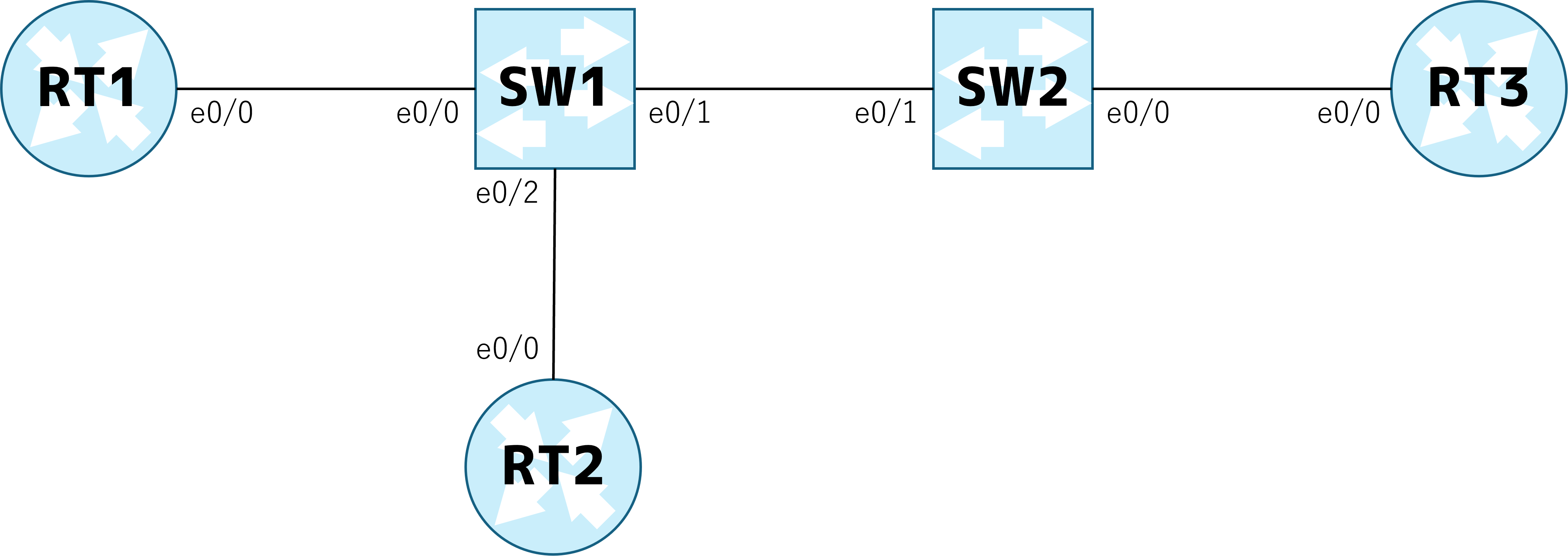
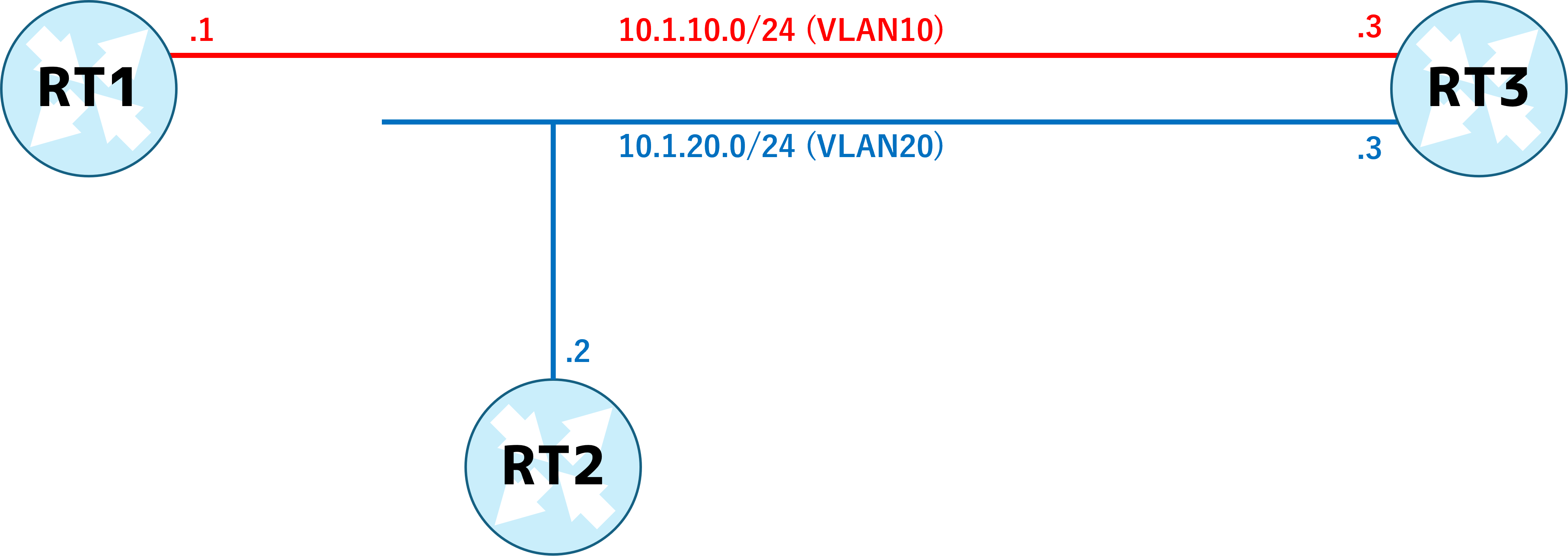
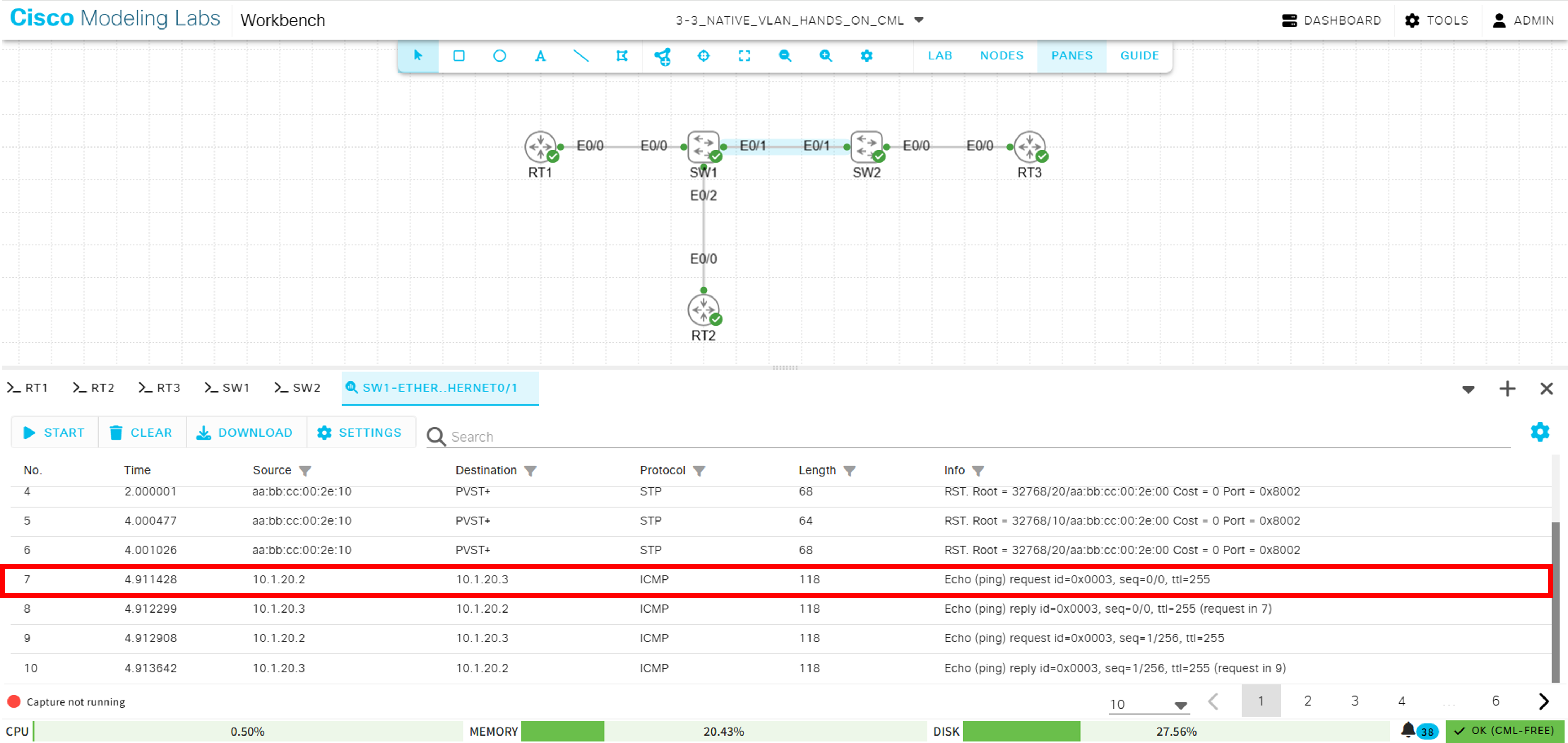
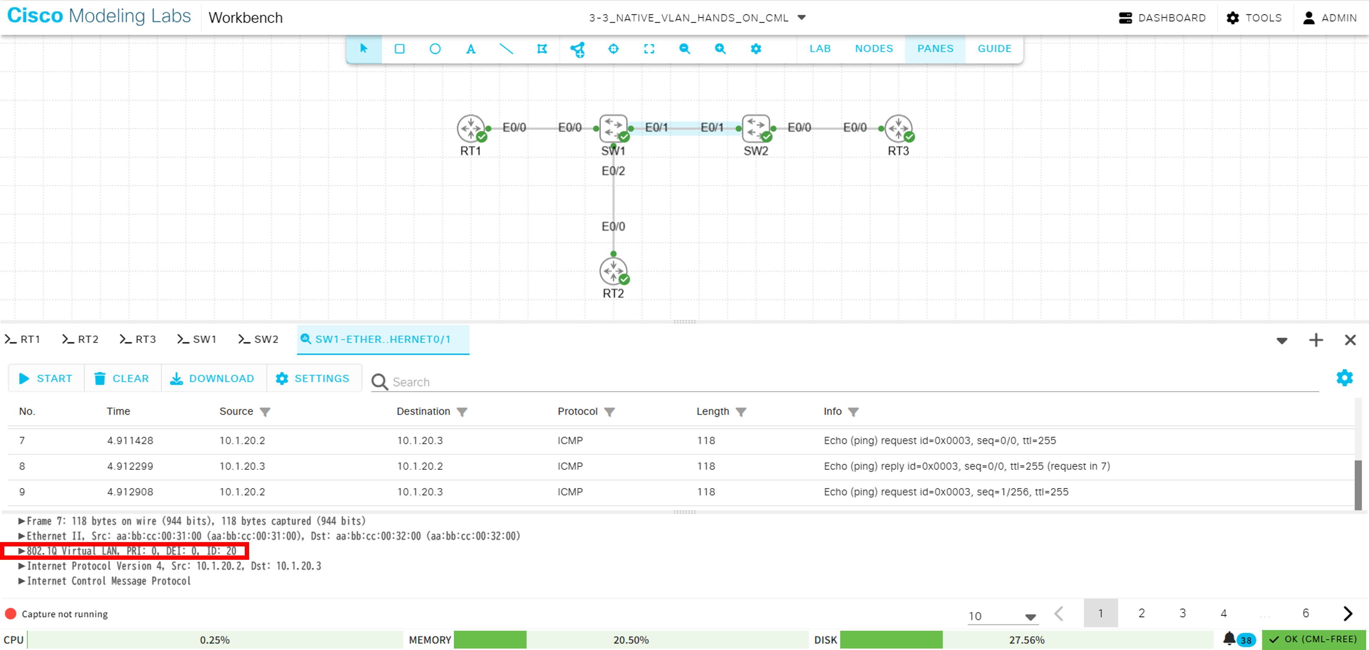
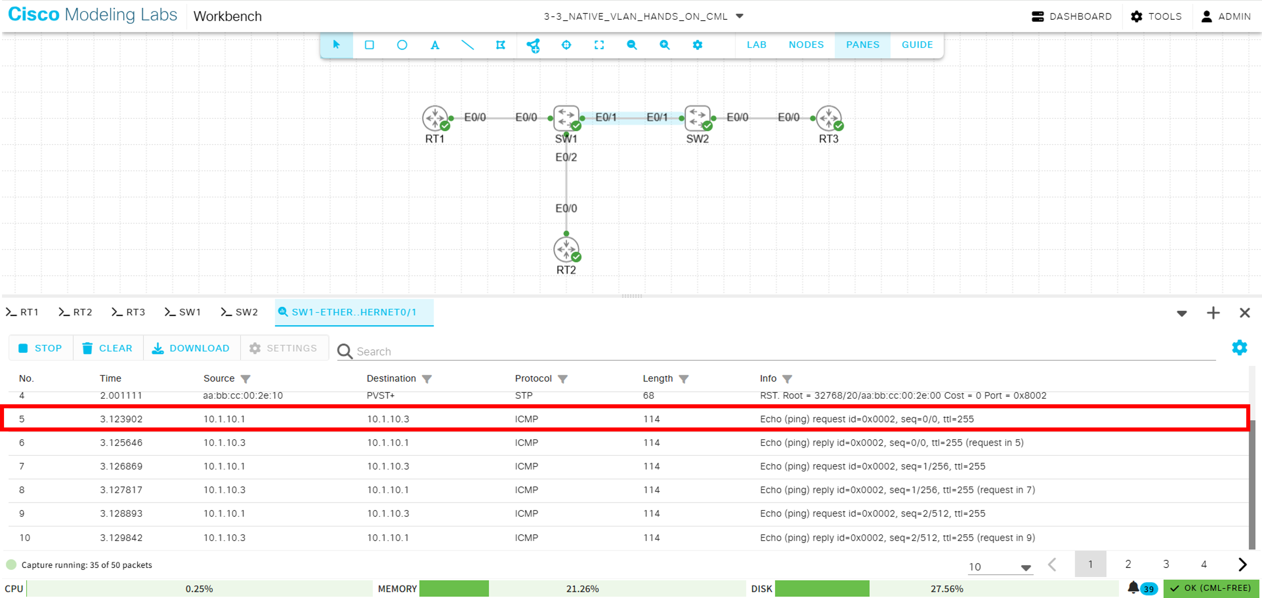
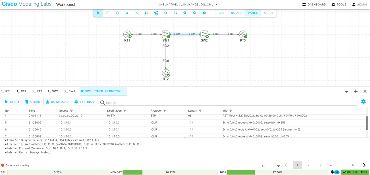
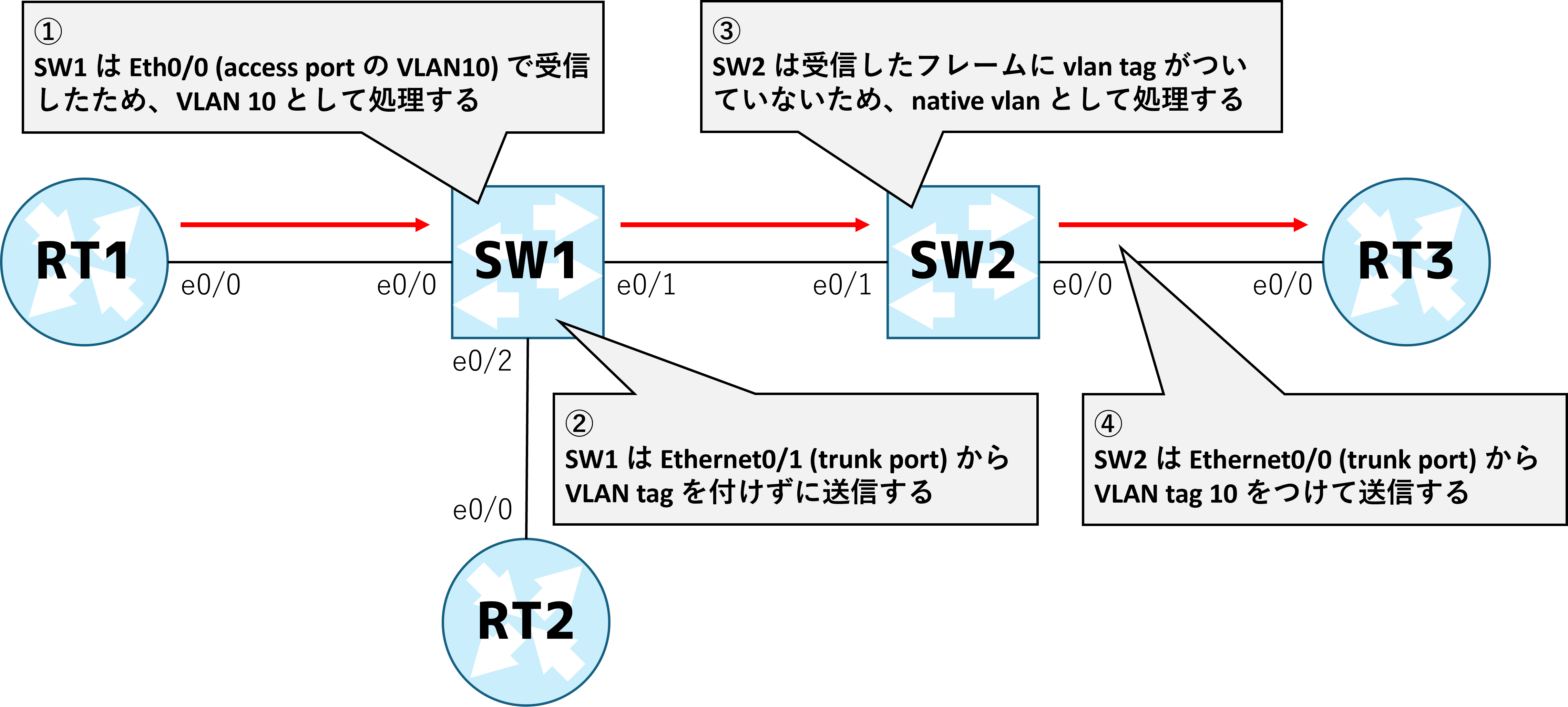
今回の構成は SW1 - SW2 間が trunk port になっており、現状は以下にようになっています。
native vlan : 1
allowed vlan : 20
SW1#show interfaces trunk

Port           Mode             Encapsulation  Status        Native vlan
Et0/1          on               802.1q         trunking      1

Port           Vlans allowed on trunk
Et0/1          20

Port           Vlans allowed and active in management domain
Et0/1          20

Port           Vlans in spanning tree forwarding state and not pruned
Et0/1          20
SW2#show interfaces trunk

Port           Mode             Encapsulation  Status        Native vlan
Et0/0          on               802.1q         trunking      1
Et0/1          on               802.1q         trunking      1

Port           Vlans allowed on trunk
Et0/0          10,20
Et0/1          20

Port           Vlans allowed and active in management domain
Et0/0          10,20
Et0/1          20

Port           Vlans in spanning tree forwarding state and not pruned
Et0/0          10,20
Et0/1          20
RT1#ping 10.1.10.3
Type escape sequence to abort.
Sending 5, 100-byte ICMP Echos to 10.1.10.3, timeout is 2 seconds:
.....
Success rate is 0 percent (0/5)
RT2#ping 10.1.20.3
Type escape sequence to abort.
Sending 5, 100-byte ICMP Echos to 10.1.20.3, timeout is 2 seconds:
!!!!!
Success rate is 100 percent (5/5), round-trip min/avg/max = 1/1/1 ms
設定後 show command で確認すると、各機器の Ethernet0/1 に設定内容が反映されていることがわかります。
SW1#show interfaces trunk

Port           Mode             Encapsulation  Status        Native vlan
Et0/1          on               802.1q         trunking      10

Port           Vlans allowed on trunk
Et0/1          10,20

Port           Vlans allowed and active in management domain
Et0/1          10,20

Port           Vlans in spanning tree forwarding state and not pruned
Et0/1          10,20
SW2#show interfaces trunk

Port           Mode             Encapsulation  Status        Native vlan
Et0/0          on               802.1q         trunking      1
Et0/1          on               802.1q         trunking      10

Port           Vlans allowed on trunk
Et0/0          10,20
Et0/1          10,20

Port           Vlans allowed and active in management domain
Et0/0          10,20
Et0/1          10,20

Port           Vlans in spanning tree forwarding state and not pruned
Et0/0          10,20
Et0/1          10,20
設定が完了したため、RT1 - RT3 (VLAN10) 間で疎通確認を行います。trunk port 間で vlan が許可されたため通信に成功していることがわかります。
RT1#ping 10.1.10.3
Type escape sequence to abort.
Sending 5, 100-byte ICMP Echos to 10.1.10.3, timeout is 2 seconds:
.!!!!
Success rate is 80 percent (4/5), round-trip min/avg/max = 1/1/2 ms
RT2#ping 10.1.20.3
Type escape sequence to abort.
Sending 5, 100-byte ICMP Echos to 10.1.20.3, timeout is 2 seconds:
!!!!!
Success rate is 100 percent (5/5), round-trip min/avg/max = 1/1/2 ms
RT1#ping 10.1.10.3
Type escape sequence to abort.
Sending 5, 100-byte ICMP Echos to 10.1.10.3, timeout is 2 seconds:
!!!!!
Success rate is 100 percent (5/5), round-trip min/avg/max = 2/2/3 ms