← 3.3 IPv4 Static route の設定 に戻る
回答を見る →
static route (ECMP) の設定(問題)
ダウンロードファイルの SHA-256
- CML:
9c2bc283f25e4b067206295e4ded3b0a5ea1412338146a6e58a8c5e9f0a26949 - EVE-NG:
88976d2ea705fb0317382c9520c2e8db635be9c08177dea94cb558310e681926
問題
- 以下の出力を得られるよう、RT1 と RT4 に static route を設定しなさい
※RT2, RT3 の両方を通る通信になっていること
RT1#traceroute 192.0.2.4 source loopback 0
Type escape sequence to abort.
Tracing the route to 192.0.2.4
VRF info: (vrf in name/id, vrf out name/id)
  1 10.1.1.2 1 msec
    10.1.3.3 0 msec
    10.1.1.2 1 msec
  2 10.1.4.4 1 msec
    10.1.2.4 1 msec
    10.1.4.4 1 msec
RT4#traceroute 192.0.2.1 source loopback 0
Type escape sequence to abort.
Tracing the route to 192.0.2.1
VRF info: (vrf in name/id, vrf out name/id)
  1 10.1.2.2 0 msec
    10.1.4.3 1 msec
    10.1.2.2 0 msec
  2 10.1.3.1 1 msec
    10.1.1.1 1 msec
    10.1.3.1 1 msec
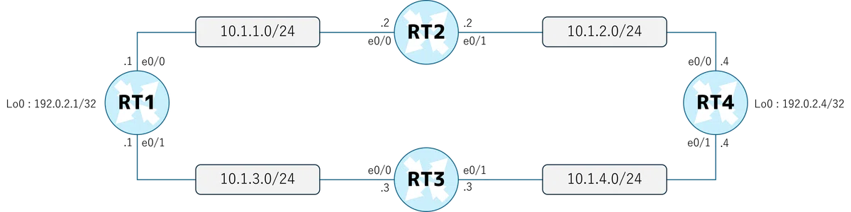
構成図
初期 Config
RT1
conf t
!
hostname RT1
!
interface Loopback0
 ip address 192.0.2.1 255.255.255.255
!
interface Ethernet0/0
 ip address 10.1.1.1 255.255.255.0
 no shutdown
!
interface Ethernet0/1
 ip address 10.1.3.1 255.255.255.0
 no shutdown
!
logging console
!
end
RT2
conf t
!
hostname RT2
!
interface Ethernet0/0
 ip address 10.1.1.2 255.255.255.0
 no shutdown
!
interface Ethernet0/1
 ip address 10.1.2.2 255.255.255.0
 no shutdown
!
ip route 192.0.2.1 255.255.255.255 Ethernet0/0 10.1.1.1
ip route 192.0.2.4 255.255.255.255 Ethernet0/1 10.1.2.4
!
logging console
!
end
RT3
conf t
!
hostname RT3
!
interface Ethernet0/0
 ip address 10.1.3.3 255.255.255.0
 no shutdown
!
interface Ethernet0/1
 ip address 10.1.4.3 255.255.255.0
 no shutdown
!
ip route 192.0.2.1 255.255.255.255 Ethernet0/0 10.1.3.1
ip route 192.0.2.4 255.255.255.255 Ethernet0/1 10.1.4.4
!
logging console
!
end
RT4
conf t
!
hostname RT4
!
interface Loopback0
 ip address 192.0.2.4 255.255.255.255
!
interface Ethernet0/0
 ip address 10.1.2.4 255.255.255.0
 no shutdown
!
interface Ethernet0/1
 ip address 10.1.4.4 255.255.255.0
 no shutdown
!
logging console
!
end
無料登録すると、ここから先がつながります
- ・ロードマップに沿って「次に読む記事」が分かる
- ・読んだ記事・解いた問題の進捗が保存される
- ・無料公開分の試験対策問題集を解いて正誤を記録できる